光栅化子模块需按相机类型单独 pip install,针孔/全景/鱼眼三选一,不装无法训练;数据集需自行从 Mip-NeRF 360 或 3DGS 官方链接下载;作者自述当前 CUDA 实现较慢,尚待优化

op43dgs
LetianHuang长期未更新针对 3D Gaussian Splatting 的投影误差做系统分析,提出最优投影策略,改善新视角合成中的渲染质量与几何一致性。
[ECCV'24] On the Error Analysis of 3D Gaussian Splatting and an Optimal Projection Strategy
暂无版本215star19fork同步于 2026-11-07 07:30 UTC
git clone [email protected]:LetianHuang/op43dgs.git
cd op43dgs
conda env create --file environment.yml
conda activate op43dgs
pip install submodules/diff-gaussian-rasterization-pinhole 硬件要求按 README 说明
README 未说明显存与 GPU 型号要求;光栅化子模块为 CUDA 实现,需编译安装,未提及 CPU 运行方式
需要 CUDA
ECCV'24 的 3D 高斯泼溅投影误差分析与最优投影策略实现,含针孔、全景、鱼眼三种光栅化后端
针对 3D Gaussian Splatting 的投影误差做系统分析,提出最优投影策略,改善新视角合成中的渲染质量与几何一致性。
核心能力
- 推导投影误差期望并求解误差函数极值
- 把每个高斯投影到各自切平面而非统一投影面
- 提供针孔、全景、鱼眼三种光栅化子模块
- 基于 3DGS 代码库,支持 Mip-NeRF 360 等数据集训练评估
- README 给出位置梯度前向与反向的完整推导
容易踩的坑
内容由模型根据 README 生成,可能不完整或不准确,以官方文档为准。看原文 README
暂无 release 数据(可能没有发版,或尚未同步)。
用户点评
登录用户的真实使用记录,可按版本和硬件筛选共 0 条
还没有人点评。第一个说出真实体验的人最有价值。

News
[2025.07.09] We release the submodule for the fisheye camera's rasterization.
[2025.05.××] 🎈 Our new work, TransparentGS, based on this repo, has been accepted by SIGGRAPH 2025.
[2024.12.25] 🎈 Our work, 360-GS, based on this repo, has been accepted by 3DV 2025.
[2024.11.14] 🖊️ Add derivation of the backward passes.
[2024.07.16] 🎈 We release the code.
[2024.07.05] Birthday of the repository.
TODO List
- Release the code (submodule for the pinhole camera's rasterization).
- Release the submodule for the panorama's rasterization.
- Release the submodule for the fisheye camera's rasterization.
- Code optimization (as mentioned in the limitation of the paper, the current CUDA implementation is slow and needs optimization).
Motivation
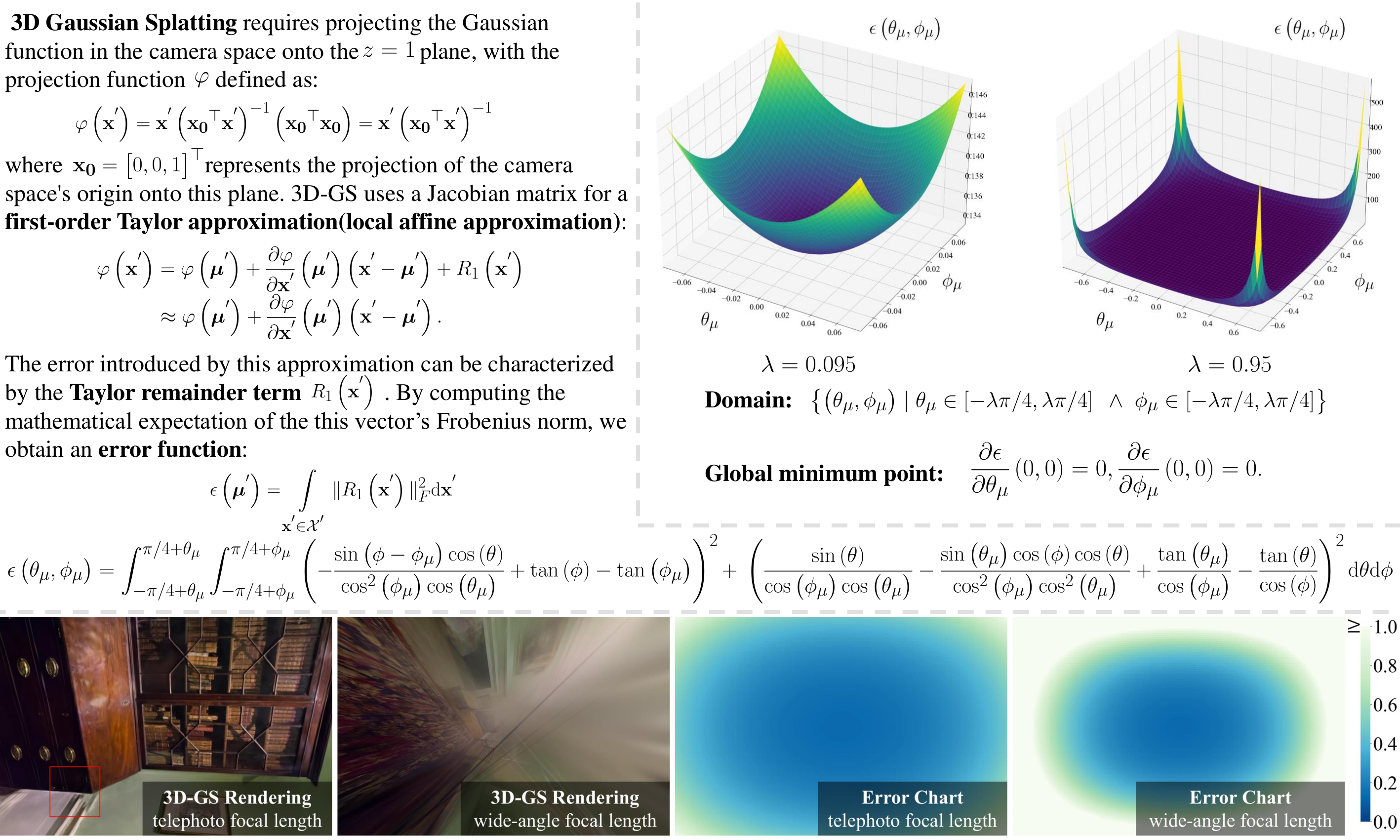
We derive the mathematical expectation of the projection error (Top left), visualize the graph of the error function under two distinct domains and analyze when this function takes extrema through methods of function optimization (Top right). We further derive the projection error function with respect to image coordinates and focal length through the coordinate transformation between image coordinates and polar coordinates and visualize this function, with the left-to-right sequence corresponding to the 3D-GS rendered images under long focal length, 3D-GS rendered images under short focal length, the error function under long focal length, and the error function under short focal length (Below).
Pipeline
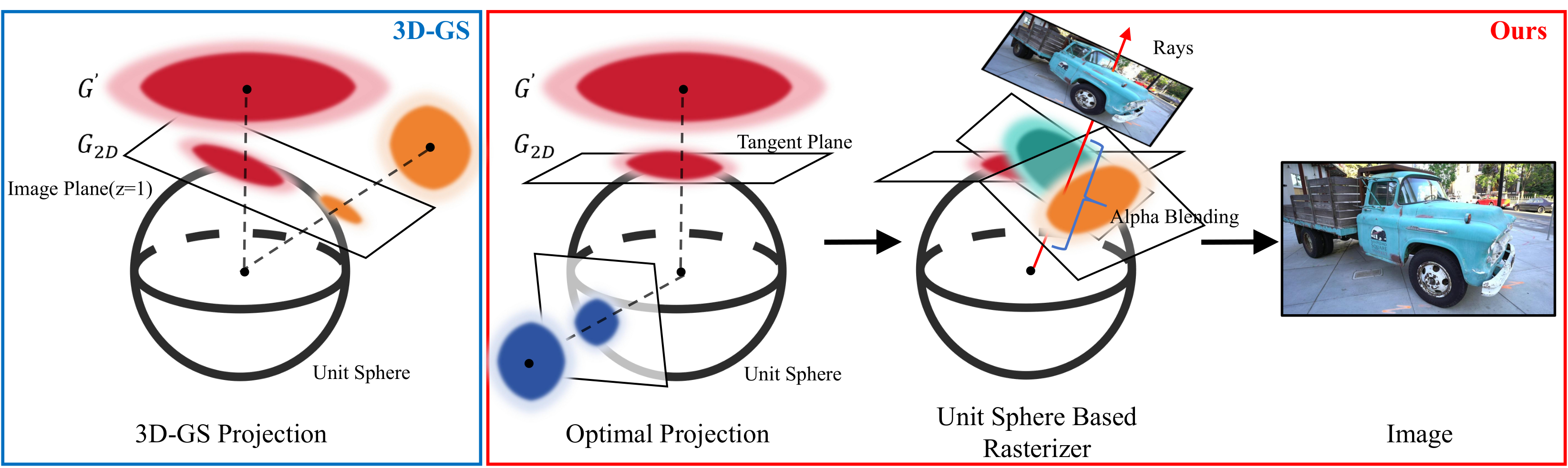
Illustration of the rendering pipeline for our Optimal Gaussian Splatting and the projection of 3D Gaussian Splatting. The blue box depicts the projection process of the original 3D-GS, which straightforwardly projects all Gaussians onto the same projection plane. In contrast, the red box illustrates our approach, where we project individual Gaussians onto corresponding tangent planes.
Installation
Clone the repository and create an anaconda environment using
git clone [email protected]:LetianHuang/op43dgs.git
cd op43dgs

SET DISTUTILS_USE_SDK=1 # Windows only
conda env create --file environment.yml
conda activate op43dgs
The repository contains several submodules, thus please check it out with
# Pinhole
pip install submodules/diff-gaussian-rasterization-pinhole
or
# Panorama
pip install submodules/diff-gaussian-rasterization-panorama
or
# Fisheye
pip install submodules/diff-gaussian-rasterization-fisheye
Dataset
Mip-NeRF 360 Dataset
Please download the data from the Mip-NeRF 360.
Tanks & Temples dataset
Please download the data from the 3D Gaussian Splatting.
Deep Blending
Please download the data from the 3D Gaussian Splatting.
Training and Evaluation
By default, the trained models use all available images in the dataset. To train them while withholding a test set for evaluation, use the --eval flag. This way, you can render training/test sets and produce error metrics as follows:
python train.py -s <path to COLMAP or NeRF Synthetic dataset> --eval # Train with train/test split
python render.py -m <path to trained model> --fov_ratio 1 # Generate renderings
--model_path / -m
Path to the trained model directory you want to create renderings for.
--skip_train
Flag to skip rendering the training set.
--skip_test
Flag to skip rendering the test set.
--quiet
Flag to omit any text written to standard out pipe.
--fov_ratio
Focal length reduction ratios.
Acknowledgements
This project is built upon 3DGS. Please follow the license of 3DGS. We thank all the authors for their great work and repos.
Citation
If you find this work useful in your research, please cite:
@inproceedings{10.1007/978-3-031-72643-9_15,
    author="Huang, Letian and Bai, Jiayang and Guo, Jie and Li, Yuanqi and Guo, Yanwen",
    title="On the Error Analysis of 3D Gaussian Splatting and an Optimal Projection Strategy",
    booktitle="Computer Vision -- ECCV 2024",
    year="2025",
    publisher="Springer Nature Switzerland",
    address="Cham",
    pages="247--263",
    isbn="978-3-031-72643-9"
}
Derivation in diff-gaussian-rasterization

About gradients of Gaussian's position
Given:
Gaussian's position in image space: $u, v$
Projection coordinates of the pixel on the unit sphere (in renderCUDA): $t_x, t_y, t_z$
Camera intrinsic parameters for pinhole: $f_x, f_y, c_x, c_y$
Forward
For the pinhole camera model, we can compute the corresponding camera coordinate based on the Gaussian position $u, v$ in image space:
$$ r_x = (u - c_x) / f_x, $$
$$ r_y = (v - c_y) / f_y, $$
$$ r_z = 1. $$
Then calculate the projection of $[r_x, r_y, r_z]^{\top}$ on the unit sphere:
$$ \mu_x = \frac{r_{x}}{\sqrt{r_{x}^{2} + r_{y}^{2} + r_{z}^{2}}}, $$
$$ \mu_y = \frac{r_{y}}{\sqrt{r_{x}^{2} + r_{y}^{2} + r_{z}^{2}}}, $$
$$ \mu_z = \frac{r_{z}}{\sqrt{r_{x}^{2} + r_{y}^{2} + r_{z}^{2}}}, $$
Subsequently, calculate the projection of $[t_x, t_y, t_z]^{\top}$ on the tangent plane $\mu_x x+\mu_y y+\mu_z z = 1$ :
$$ \mathbf{x}_{2D}=\begin{bmatrix} \frac{t_x}{\mu_x t_x + \mu_y t_y + \mu_z t_z} \newline \frac{t_y}{\mu_x t_x + \mu_y t_y + \mu_z t_z} \newline \frac{t_z}{\mu_x t_x + \mu_y t_y + \mu_z t_z} \end{bmatrix} $$
Then, calculate the matrix $\mathbf{Q}$ based on Equation 18 in the paper:
$$ \mathbf{Q}=\begin{bmatrix} \frac{\mu_{z}}{\sqrt{\mu_{x}^{2} + \mu_{z}^{2}}} & 0 & - \frac{\mu_{x}}{\sqrt{\mu_{x}^{2} + \mu_{z}^{2}}} \newline - \frac{\mu_{x} \mu_{y}}{\sqrt{\mu_{x}^{2} + \mu_{z}^{2}} \sqrt{\mu_{x}^{2} + \mu_{y}^{2} + \mu_{z}^{2}}} & \frac{\sqrt{\mu_{x}^{2} + \mu_{z}^{2}}}{\sqrt{\mu_{x}^{2} + \mu_{y}^{2} + \mu_{z}^{2}}} & - \frac{\mu_{y} \mu_{z}}{\sqrt{\mu_{x}^{2} + \mu_{z}^{2}} \sqrt{\mu_{x}^{2} + \mu_{y}^{2} + \mu_{z}^{2}}} \newline \frac{\mu_{x}}{\sqrt{\mu_{x}^{2} + \mu_{y}^{2} + \mu_{z}^{2}}} & \frac{\mu_{y}}{\sqrt{\mu_{x}^{2} + \mu_{y}^{2} + \mu_{z}^{2}}} & \frac{\mu_{z}}{\sqrt{\mu_{x}^{2} + \mu_{y}^{2} + \mu_{z}^{2}}}\end{bmatrix}\text{.} $$
Subsequently, the projection of the pixel onto the tangent plane after transformerd into the local coordinate system can be obtained through the $\mathbf{Q}$ matrix (The origin of the local coordinate system is the projection of the Gaussian mean onto the tangent plane):
$$ \begin{bmatrix} u_{pixf} \newline v_{pixf} \newline 1 \end{bmatrix}=\mathbf{Q}\mathbf{x}_{2D} $$
$$ =\begin{bmatrix}\frac{- \mu_{x} t_{z} + \mu_{z} t_{x}}{\sqrt{\mu_{x}^{2} + \mu_{z}^{2}} \left(\mu_{x} t_{x} + \mu_{y} t_{y} + \mu_{z} t_{z}\right)} \newline \frac{- \mu_{y} \left(\mu_{x} t_{x} + \mu_{z} t_{z}\right) + t_{y} \left(\mu_{x}^{2} + \mu_{z}^{2}\right)}{\sqrt{\mu_{x}^{2} + \mu_{z}^{2}} \sqrt{\mu_{x}^{2} + \mu_{y}^{2} + \mu_{z}^{2}} \left(\mu_{x} t_{x} + \mu_{y} t_{y} + \mu_{z} t_{z}\right)} \newline 1\end{bmatrix}. $$
Finally, the difference between the projection of the Gaussian mean and the pixel projection onto the tangent plane can be calculated:
$$ d_x = -u_{pixf},\quad d_y = -v_{pixf} $$
Backward
It is recommended to use scientific computing tools to compute the gradient!
First, calculate the partial derivatives of $d_x, d_y$ with respect to $r_x, r_y$:
$$ \frac{\partial d_x}{\partial r_x}=\frac{\partial d_x}{\partial \mu_x}\frac{\partial \mu_x}{\partial r_x}+\frac{\partial d_x}{\partial \mu_y}\frac{\partial \mu_x}{\partial r_x}+\frac{\partial d_x}{\partial \mu_z}\frac{\partial \mu_z}{\partial r_x},\quad \frac{\partial d_x}{\partial r_y}=\frac{\partial d_x}{\partial \mu_x}\frac{\partial \mu_x}{\partial r_y}+\frac{\partial d_x}{\partial \mu_y}\frac{\partial \mu_x}{\partial r_y}+\frac{\partial d_x}{\partial \mu_z}\frac{\partial \mu_z}{\partial r_y}, $$
$$ \frac{\partial d_y}{\partial r_x}=\frac{\partial d_y}{\partial \mu_x}\frac{\partial \mu_x}{\partial r_x}+\frac{\partial d_y}{\partial \mu_y}\frac{\partial \mu_x}{\partial r_x}+\frac{\partial d_y}{\partial \mu_z}\frac{\partial \mu_z}{\partial r_x},\quad \frac{\partial d_y}{\partial r_y}=\frac{\partial d_y}{\partial \mu_x}\frac{\partial \mu_x}{\partial r_y}+\frac{\partial d_y}{\partial \mu_y}\frac{\partial \mu_x}{\partial r_y}+\frac{\partial d_y}{\partial \mu_z}\frac{\partial \mu_z}{\partial r_y}. $$
Then, calculate the gradient of $r_x, r_y$ with respect to $u, v$ (gradients related to the camera model):
$$ \frac{\partial r_x}{\partial u}=1 / f_x,\quad \frac{\partial r_y}{\partial v}=1 / f_y. $$
Using the chain rule, we can obtain:
$$ \frac{\partial d_x}{\partial u}=\frac{\partial d_x}{\partial r_x}\frac{\partial r_x}{\partial u}, \quad \frac{\partial d_x}{\partial v}=\frac{\partial d_x}{\partial r_y}\frac{\partial r_y}{\partial v}, $$
$$ \frac{\partial d_y}{\partial u}=\frac{\partial d_y}{\partial r_x}\frac{\partial r_x}{\partial u}, \quad \frac{\partial d_y}{\partial v}=\frac{\partial d_y}{\partial r_y}\frac{\partial r_y}{\partial v}. $$

gaussian-splatting
graphdeco-inria·Python
3D Gaussian Splatting 的官方参考实现,用高斯点云做辐射场重建,实现实时可交互的逼真场景渲染。
3D高斯泼溅+43D 重建硬核
24453+213.5k2025-10-17 14:28 UTC
instant-ngp
NVlabs·Cuda
用多分辨率哈希编码把 NeRF、SDF 等神经图形基元的训练从几小时压到几秒,实时渲染三维场景。
神经辐射场+43D 重建硬核
17593+52.1kv2.02026-02-02 12:32 UTC
Open3D
isl-org·C++
Open3D 是一个现代 3D 数据处理库,提供点云、网格、RGB-D 和 3D 可视化等算法与工具,支持 C++ 和 Python,可用于 3D 感知、重建与机器学习研究。
3D数据处理+43D 重建进阶
14193+122.6kv0.20.02026-11-10 19:59 UTC
colmap
colmap·C++
从多张照片重建三维场景的 C++ 工具,集成了运动恢复结构(SfM)和多视图立体(MVS),可输出相机位姿与稠密点云。
三维重建+43D 重建进阶
13197+232.2kdatasets-eth3d-undistorted-v12026-11-10 08:51 UTC